
页面加载中,请稍候
来源:开源Linux发布时间:2023-05-231069浏览
询问 AI
来源:网络技术联盟站
今天给大家带来实验实战部分,一共介绍三家厂商的例子:
华三的例子可以参考华为,锐捷的例子可以参考思科。
建议先收藏本文哦,防止看完手滑后找不到了。
让我们直接开始!
OSPF(Open Shortest Path First开放式最短路径优先)是IETF组织开发的一个基于链路状态的内部网关协议(Interior Gateway Protocol)。目前针对IPv4协议使用的是OSPF Version 2(RFC2328)。
OSPF具有适应范围广、收敛快、无自环、区域划分、等价路由、支持验证、组播发送等特点。由于OSPF具有以上优势,使得OSPF作为目前主流的IGP协议被广泛应用于各个行业,例如企业、运营商、政府、金融、教育、医疗等。
OSPF采用分层设计的结构,并且具有丰富的路由策略控制功能,能够适用于各种不同规模、不同组网结构的应用场景。因此在部署IGP协议的时候,OSPF经常是用户的首选方案。
如图所示,网络中有三台交换机。现在需要实现三台交换机之间能够互通,且以后能依据SwitchA和SwitchB为主要的业务设备来继续扩展整个网络。
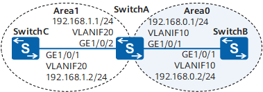
采用如下的思路配置OSPF基本功能:
配置SwitchA。SwitchB和SwitchC的配置与SwitchA类似。
<HUAWEI>system-view
[HUAWEI]sysnameSwitchA
[SwitchA]vlanbatch1020
[SwitchA]interfacegigabitethernet1/0/1
[SwitchA-GigabitEthernet1/0/1]portlink-typetrunk
[SwitchA-GigabitEthernet1/0/1]porttrunkallow-passvlan10
[SwitchA-GigabitEthernet1/0/1]quit
[SwitchA]interfacegigabitethernet1/0/2
[SwitchA-GigabitEthernet1/0/2]portlink-typetrunk
[SwitchA-GigabitEthernet1/0/2]porttrunkallow-passvlan20
[SwitchA-GigabitEthernet1/0/2]quit
配置SwitchA。SwitchB和SwitchC的配置与SwitchA类似。
[SwitchA]interfacevlanif10
[SwitchA-Vlanif10]ipaddress192.168.0.124
[SwitchA-Vlanif10]quit
[SwitchA]interfacevlanif20
[SwitchA-Vlanif20]ipaddress192.168.1.124
[SwitchA-Vlanif20]quit
配置SwitchA。
[SwitchA]ospf1router-id10.1.1.1//创建进程号为1,RouterID为10.1.1.1的OSPF进程
[SwitchA-ospf-1]area0//创建area0区域并进入area0视图
[SwitchA-ospf-1-area-0.0.0.0]network192.168.0.00.0.0.255//配置area0所包含的网段
[SwitchA-ospf-1-area-0.0.0.0]quit
[SwitchA-ospf-1]area1//创建area1区域并进入area1视图
[SwitchA-ospf-1-area-0.0.0.1]network192.168.1.00.0.0.255//配置area1所包含的网段
[SwitchA-ospf-1-area-0.0.0.1]return
配置SwitchB。
[SwitchB]ospf1router-id10.2.2.2
[SwitchB-ospf-1]area0
[SwitchB-ospf-1-area-0.0.0.0]network192.168.0.00.0.0.255
[SwitchB-ospf-1-area-0.0.0.0]return
配置SwitchC。
[SwitchC]ospf1router-id10.3.3.3
[SwitchC-ospf-1]area1
[SwitchC-ospf-1-area-0.0.0.1]network192.168.1.00.0.0.255
[SwitchC-ospf-1-area-0.0.0.1]return
查看SwitchA的OSPF邻居。
<SwitchA>displayospfpeer

OSPFProcess1withRouterID10.1.1.1
Neighbors

Area0.0.0.0interface192.168.0.1(Vlanif10)'sneighbors
RouterID:10.2.2.2Address:192.168.0.2
State:FullMode:NbrisMasterPriority:1
DR:192.168.0.2BDR:192.168.0.1MTU:0
Deadtimerduein36sec
Retranstimerinterval:5
Neighborisupfor00:15:04
AuthenticationSequence:[0]

Neighbors

Area0.0.0.1interface192.168.1.1(Vlanif20)'sneighbors
RouterID:10.3.3.3Address:192.168.1.2
State:FullMode:NbrisMasterPriority:1
DR:192.168.1.2BDR:192.168.1.1MTU:0
Deadtimerduein39sec
Retranstimerinterval:5
Neighborisupfor00:07:32
AuthenticationSequence:[0]
查看SwitchC的OSPF路由信息。
<SwitchC>displayospfrouting

OSPFProcess1withRouterID10.3.3.3
RoutingTables

RoutingforNetwork
DestinationCostTypeNextHopAdvRouterArea
192.168.1.0/241Transit192.168.1.210.3.3.30.0.0.1
192.168.0.0/242Inter-area192.168.1.110.1.1.10.0.0.1

TotalNets:2
IntraArea:1InterArea:1ASE:0NSSA:0
由以上回显可以看出,SwitchC有到192.168.0.0/24网段的路由,且此路由被标识为区域间路由。
查看SwitchB的路由表,并使用Ping测试SwitchB和SwitchC的连通性。
<SwitchB>displayospfrouting

OSPFProcess1withRouterID10.2.2.2
RoutingTables

RoutingforNetwork
DestinationCostTypeNextHopAdvRouterArea
192.168.0.0/241Transit192.168.0.210.2.2.20.0.0.0
192.168.1.0/242Inter-area192.168.0.110.1.1.10.0.0.0

TotalNets:2
IntraArea:1InterArea:1ASE:0NSSA:0
由以上回显可以看出,SwitchB有到192.168.1.0/24网段的路由,且此路由被标识为区域间路由。
在SwitchB上使用Ping测试SwitchB和SwitchC之间的连通性。
<SwitchB>ping192.168.1.2
PING192.168.1.2:56databytes,pressCTRL_Ctobreak
Replyfrom192.168.1.2:bytes=56Sequence=1ttl=254time=62ms
Replyfrom192.168.1.2:bytes=56Sequence=2ttl=254time=16ms
Replyfrom192.168.1.2:bytes=56Sequence=3ttl=254time=62ms
Replyfrom192.168.1.2:bytes=56Sequence=4ttl=254time=94ms
Replyfrom192.168.1.2:bytes=56Sequence=5ttl=254time=63ms

---192.168.1.2pingstatistics---
5packet(s)transmitted
5packet(s)received
0.00%packetloss
round-tripmin/avg/max=16/59/94ms
SwitchA的配置文件
#
sysnameSwitchA
#
vlanbatch1020
#
interfaceVlanif10
ipaddress192.168.0.1255.255.255.0
#
interfaceVlanif20
ipaddress192.168.1.1255.255.255.0
#
interfaceGigabitEthernet1/0/1
portlink-typetrunk
porttrunkallow-passvlan10
#
interfaceGigabitEthernet1/0/2
portlink-typetrunk
porttrunkallow-passvlan20
#
ospf1router-id10.1.1.1
area0.0.0.0
network192.168.0.00.0.0.255
area0.0.0.1
network192.168.1.00.0.0.255
#
return
SwitchB的配置文件
#
sysnameSwitchB
#
vlanbatch10
#
interfaceVlanif10
ipaddress192.168.0.2255.255.255.0
#
interfaceGigabitEthernet1/0/1
portlink-typetrunk
porttrunkallow-passvlan10
#
ospf1router-id10.2.2.2
area0.0.0.0
network192.168.0.00.0.0.255
#
return
SwitchC的配置文件
#
sysnameSwitchC
#
vlanbatch20
#
interfaceVlanif20
ipaddress192.168.1.2255.255.255.0
#
interfaceGigabitEthernet1/0/1
portlink-typetrunk
porttrunkallow-passvlan20
#
ospf1router-id10.3.3.3
area0.0.0.1
network192.168.1.00.0.0.255
#
return

R1(config)#interfacefastEthernet0/0
R1(config-if)#ipaddress172.16.1.1255.255.255.0
R1(config-if)#noshutdown
R1(config)#interfaces2/0
R1(config-if)#ipadd192.168.1.5255.255.255.252
R1(config-if)#clockrate64000
R1(config-if)#noshutdown
R2(config)#interfaces3/0
R2(config-if)#ipadd192.168.1.6255.255.255.252
R2(config-if)#noshutdown
R2(config)#interfacefa1/0
R2(config-if)#ipadd10.10.10.1255.255.255.0
R2(config-if)#noshutdown
R1(config)#routerospf1
启动ospf进程,进程ID为1(进程ID取值范围是1-65535中的一个整数),此进程号只是本地的一个标识,具有本地意义,与同一个区域中的OSPF路由器进程号没有关系,进程号不同不影响邻接关系的建立。
R1(config-router)#network172.16.1.00.0.0.255area0
宣告网络,即定义参与OSPF进程的接口或网络,并指定其运行的区域(区域0为骨干区域),通配符掩码用来控制要宣告的范围,任何在此地址范围内的接口都运行OSPF协议,发送和接收OSPF报文,0表示精确匹配,将检查匹配地址中对应位,1表示任意匹配,不检查匹配地址中对应位。
R1(config-router)#network192.168.1.40.0.0.3area0
R2(config)#routerospf1
R2(config-router)#network192.168.1.40.0.0.3area0
R2(config-router)#network10.10.10.00.0.0.255area0
注意事项:
R1#showiproute查看路由表
R1#showipprotocols查看已配置并运行的路由协议
R1#showipospfneighbor查看邻居表
R1#showipospfneighbordetail显示邻居路由器的详细信息
R1#showipospfdatabase查看拓扑表,即链路状态数据库
R1#showipospfinterface查看所有运行OSPF的接口信息
R1#showipospfinterfaces2/0查看s2/0接口的OSPF信息
R1#showinterfacess2/0查看路由器的接口信息
查看Router ID号
R1#showipprotocols
R1#showipospf1
R2#showipospfneighbor
(1)下面更改接口带宽以影响链路Cost
R1(config)#interfaces2/0
R1(config-if)#bandwidth64
查看更改结果
R1#showinterfacess2/0查看带宽值
R1#showipospfinterfaces2/0查看开销值
R1#showiprouteospf查看路由表,看度量值的变化
(2)下面直接更改接口相关Cost
R1(config)#interfaces2/0
R1(config-if)#ipospfcost200
查看更改结果
R1#showipospfinterfaces2/0查看开销值
R1#showiprouteospf查看路由表,看度量值的变化
R1#showinterfacess2/0查看带宽值有无变化
R1#debugipospfevents监测OSPF事件
R1#undebugall关闭
R1#debugipospfpacket监测OSPF包的传输(PT模拟器没有该命令)
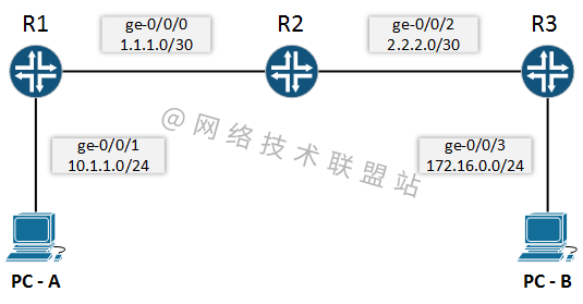
首先,为所有设备配置 IP 地址。
R1:
setinterfacesge-0/0/0unit0familyinetaddress1.1.1.1/30
setinterfacesge-0/0/1unit0familyinetaddress10.1.1.1/2
4
R2:
setinterfacesge-0/0/0unit0familyinetaddress1.1.1.2/30
setinterfacesge-0/0/2unit0familyinetaddress2.2.2.1/30
R3:
setinterfacesge-0/0/2unit0familyinetaddress2.2.2.2/30
setinterfacesge-0/0/3unit0familyinetaddress172.16.0.1/30
PC:
PC-A:10.1.1.10/24
PC-B:172.16.0.10/24
然后将通过启用它转到 OSPF 配置,要在 JunOS 中启用 OSPF,需要定义它将运行的接口以及接口将附加到的区域。
R1:
setprotocolsospfarea0.0.0.0interfacege-0/0/0.0
setprotocolsospfarea0.0.0.0interfacege-0/0/1.0
在这里,我们在接口 ge-0/0/0.0 和路由器 R1 的接口 ge-0/0/1.0 上配置了 OSPF 区域 0 (0.0.0.0)。现在对其他两个路由器做同样的事情。
R2:
setprotocolsospfarea0.0.0.0interfacege-0/0/0.0
setprotocolsospfarea0.0.0.0interfacege-0/0/2.0
R3:
setprotocolsospfarea0.0.0.0interfacege-0/0/2.0
setprotocolsospfarea0.0.0.0interfacege-0/0/3.0
要在 Juniper 上验证 OSPF,我们需要使用show ospf neighbor命令,该命令将显示当前与其他路由器的 OSPF 邻居关系。
root@R1>showospfneighbor
AddressInterfaceStateIDPriDead
1.1.1.2ge-0/0/0.0Full1.1.1.212839
我们可以从 R1 的上述输出中看到,其中 OSPF 邻居关系是使用处于完整状态(活动)的 ge-0/0/0.0 接口建立的。
如果我们想检查 OSPF 数据库中现在有哪些接口,那么我们需要使用show ospf interface命令。
下面是路由器 R1 的输出。
root@R1>showospfinterface
InterfaceStateAreaDRIDBDRIDNbrs
ge-0/0/0.0DR0.0.0.01.1.1.11.1.1.21
ge-0/0/1.0DR0.0.0.01.1.1.10.0.0.00
现在,让我们检查路由表。
root@R1>showroute

inet.0:7destinations,7routes(7active,0holddown,0hidden)
+=ActiveRoute,-=LastActive,*=Both

1.1.1.0/30*[Direct/0]01:35:01
>viage-0/0/0.0
1.1.1.1/32*[Local/0]01:35:01
Localviage-0/0/0.0
2.2.2.0/30*[OSPF/10]00:09:23,metric2
>to1.1.1.2viage-0/0/0.0
10.1.1.0/24*[Direct/0]01:35:01
>viage-0/0/1.0
10.1.1.1/32*[Local/0]01:35:01
Localviage-0/0/1.0
172.16.0.0/24*[OSPF/10]00:09:22,metric3
>to1.1.1.2viage-0/0/0.0
224.0.0.5/32*[OSPF/10]00:51:38,metric1
MultiRecv
路由表清楚地显示,我们使用 OSPF 协议通过 R2 接收来自 R3 的路由以及我们的路由。
最后,我们将通过从 PC-A ping 到 PC-B 来验证它。
PC-A:\>ping172.16.0.10

Pinging172.16.0.10with32bytesofdata:
Replyfrom172.16.0.10:bytes=32time=4msTTL=64
Replyfrom172.16.0.10:bytes=32time=3msTTL=64
Replyfrom172.16.0.10:bytes=32time=1msTTL=64
Replyfrom172.16.0.10:bytes=32time=6msTTL=64

Pingstatisticsfor172.16.0.10:
Packets:Sent=4,Received=4,Lost=0(0%loss),
Approximateroundtriptimesinmilli-seconds:
Minimum=1ms,Maximum=6ms,Average=3ms
本文介绍了华为、思科、瞻博网络三家厂商的 OSPF 实验配置,大家可以收藏备用哦。
新闻来源:开源Linux,文中所述为作者独立观点,不代表icspec立场。更多精彩资讯请下载icspec App。如对本稿件有异议,请联系微信客服specltkj。
暂无评论哦,快来评论一下吧!

2026-06-09
2026-06-24

2026-06-11